

An e-bike is only as reliable as the weakest connection in its wiring system, and in most field failures that weak point is not the motor or the controller — it is an unprotected splice or a cheap connector that let water in. A properly engineered Ebike 9-Pin 1-to-3 Waterproof Wiring Harness solves this problem at the design level: it merges the three motor phase wires, the five Hall-sensor signals and one speed or reserved line into a single sealed, over-molded cable, then branches into exactly the connectors your controller, display, throttle and lighting circuits need. This guide walks through the complete engineering picture — pin assignments, ingress protection, cable gauge selection, electrical limits, branching topologies, installation practice and factory quality control — so that OEM product managers, assembly plants and serious DIY builders can specify a harness that survives years of rain, mud, vibration and temperature swings. If you read only one section, read the cable-gauge table and the installation checklist; together they prevent the majority of warranty returns we see in the e-mobility industry.
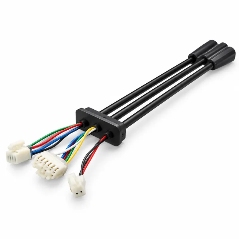
A 9-pin 1-to-3 harness is a pre-assembled cable system with one main trunk that splits into three separate output legs. On a typical electric bike or e-scooter, the main trunk runs from the controller compartment toward the hub motor, while the three branches distribute power and signals to the circuits that would otherwise require three loose, separately sealed connections. A common configuration is a 9-pin male plug for the motor (phase wires plus Hall signals), a 9-pin female pass-through or extension leg, and a smaller 2-pin to 5-pin leg for a speed sensor, brake cut-off, light or throttle circuit. The exact mix is customizable, which is precisely why this product category exists.
The value of the design is consolidation. Without it, an assembly plant must join individual phase wires, Hall wires and sensor wires using heat-shrink splices or open crimp terminals, each of which is a potential water entry point and a potential vibration failure. With a molded 1-to-3 harness, every junction is sealed inside an over-molded boot, every connector uses a captive sealing ring, and the assembly becomes essentially plug-and-play on the production line. Installation time drops, wiring errors drop, and the finished bike looks cleaner because a single cable run replaces a nest of taped wires.
It is worth distinguishing this product from a plain extension cable. A 9-pin extension cable simply lengthens an existing connection; a 1-to-3 harness redistributes circuits. The branching geometry, the pin count of each leg, the wire gauge in each leg and the sealing level of each connector can all differ, because each leg serves a different electrical function. That flexibility is what makes the harness a system component rather than an accessory.
Almost every hub-motor drive system on the market converges on the same nine-signal architecture, which is why a 9-pin waterproof connector became the de facto interface between motor and controller. The nine positions are normally allocated as follows:
| Pin | Function | Typical Wire Color | Notes |
|---|---|---|---|
| 1 | Phase C | Yellow | Motor power leg C, switched by controller FET bridge |
| 2 | Phase B | Green | Motor power leg B |
| 3 | Phase A | Red | Motor power leg A |
| 4 | Hall power (+5 V) | Red | Feeds the three Hall-effect sensors inside the motor |
| 5 | Hall signal H3 | Yellow | Rotor position, 120° electrical spacing |
| 6 | Hall signal H2 | Green | Rotor position |
| 7 | Hall signal H1 | Blue | Rotor position |
| 8 | Hall ground | Black | Signal ground return for sensor circuits |
| 9 | Speed sensor / reserved | White | Pulse line from an internal or external speed sensor |
Three of the nine contacts carry motor current; the remaining six carry low-current signals. This 3-power-plus-6-signal split is the reason many harness designs physically separate the power and signal cores into two internal groups, sometimes even into two connector cavities within one housing. Separating them limits electromagnetic coupling between the phase wires, which switch high currents at PWM frequency, and the millivolt-level Hall signals the controller uses to commutate the motor. When Hall signals pick up switching noise, the classic symptoms are jerky launch, hesitation at low speed and error codes on the display.
Color conventions are strong but not universal. Reputable harness suppliers document their pinout on a drawing for every order, and professional assemblers verify continuity with a multimeter before first power-up rather than trusting color alone. If you are integrating a harness into an existing fleet, request the pinout drawing and keep it with the bike's service records; it turns a future troubleshooting session from guesswork into a five-minute check.
An e-bike lives outdoors. It is parked in rain, ridden through puddles, washed with a hose and stored in humid garages. Water inside a connector causes two distinct failure mechanisms: immediate short circuits between adjacent contacts, and slower galvanic corrosion that raises contact resistance over weeks until the connection drops out intermittently. Because the motor connector carries both high current and precision signals, it is the single most water-exposed critical joint on the vehicle, and its sealing quality largely defines the drive system's weather reputation.
Ingress protection is graded by the IP code. The ratings you will encounter in harness specification sheets are:
| Rating | Meaning | Suitable For |
|---|---|---|
| IP65 | Protected against water jets from any direction | Light rain and splash; fair-weather commuters |
| IP67 | Immersion up to 1 m for 30 minutes | All-weather commuting, shared fleets, rainy climates |
| IP68 | Continuous immersion beyond 1 m, conditions agreed with maker | Cargo bikes, e-mopeds, flood-prone delivery routes |
Achieving IP67 consistently in mass production is harder than printing it on a datasheet. It depends on three details working together: a compressible sealing ring that is captured so it cannot be installed backwards, an over-molded rear boot where the cable enters the shell, and a potting or multi-durometer overmold that blocks capillary paths between the wire strands and the jacket. When auditing a supplier, ask specifically how the cable entry is sealed — the crimp zone behind the contacts is where water sneaks in. A well-made harness will also specify a mating depth tolerance so the seal compresses to the designed amount every cycle, instead of relying on the user to push hard enough.
Do not forget the unmated state. During assembly, shipping or spare-part storage, connectors sit open for days or months. A protective cap during storage, and a design that keeps the contact face recessed behind the seal lip, protects the joint before it is ever mated.
Undersized phase conductors waste battery energy as heat and can melt insulation at sustained high load; oversized conductors waste money and routing space. The industry has converged on practical cross-sections by motor rating, and deviating more than one size from these values is a design smell:
| Motor Power | Vehicle Class | Recommended Phase Conductor | Typical Overall Cable OD |
|---|---|---|---|
| 250 – 350 W | EU city / trekking e-bikes | 1.2 mm² | ≈ 6 – 8 mm |
| 500 – 750 W | Speed pedelecs, e-MTB, cargo | 1.5 mm² | ≈ 8 – 10 mm |
| 750 – 1000 W | Off-road and utility e-bikes | 2.0 mm² | ≈ 10 – 12 mm |
| 1000 W and above | E-mopeds and light e-motorcycles | 2.5 – 4.0 mm² | up to ≈ 13 mm |
Signal conductors inside the same jacket are typically 0.2 – 0.35 mm²; they carry milliamps and their gauge is chosen for mechanical robustness, not current. Stranding matters as much as cross-section: a fine-stranded, high-flex copper conductor with tinned strands resists work-hardening and oxidation far better than a coarse-strand cheap cable, which is why two harnesses with identical gauge tables can age completely differently.
Voltage drop is the quiet cost of an undersized run. On a 36 V system a half-volt lost in the harness is barely noticeable; on a 24 V system the same drop visibly reduces peak power and trips low-voltage cut-offs earlier in the discharge curve. When you customize harness length, recalculate the drop: for a 1.5 mm² phase conductor, a two-meter round trip at 15 A loses roughly 0.35 V. If your controller sits far from the motor — long-tail cargo bikes are the usual offender — either shorten the run, step up the gauge or accept the measured loss deliberately.
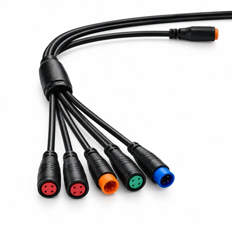
The "1-to-3" descriptor covers several distinct wiring strategies, and choosing the right one starts from a simple question: what three circuits need to leave the controller compartment through one sealed trunk?
Topology A — Motor pass-through plus accessories. The main trunk carries the full 9-pin motor interface; one branch is the 9-pin motor plug, a second branch is a 9-pin female extension that lets a future motor swap happen without cutting anything, and the third branch breaks out to a 2- or 3-pin sealed connector for a speed sensor or brake cut-off. This is the most common configuration for hub-motor city bikes and the closest match to a standard Ebike 9-Pin 1-to-3 Waterproof Wiring Harness.
Topology B — Display and control split. One trunk from the battery-side controller feeds the handlebar, where it splits into a display connector, a throttle connector and a light or horn connector. Handlebar space is tight and rotating joints punish stiff cables, so this topology uses shorter, more flexible branch legs with a tighter bend radius.
Topology C — Shared-fleet sensor fan-out. Shared-fleet and delivery bikes add GPS trackers, IoT telemetry boxes and extra lighting on top of the standard drive wiring. A 1-to-3 harness with one leg dedicated to a 4- or 5-pin telemetry connector keeps all of that add-on wiring on one sealed trunk instead of a chain of inline splices that fleets cannot audit.
Whichever topology you choose, keep signal legs away from the phase-wire leg inside the trunk. A physically twisted or cross-coupled layout is acceptable at these frequencies, but a branch that runs the Hall wires strapped directly against the phase conductors for their whole length invites noise. Good harness drawings specify the internal routing; if a supplier's drawing does not, ask what their standard practice is.
The mechanical life of a harness is decided at two places: where the cable enters the connector, and where the branches meet the trunk. Both are solved by over-molding — injecting a bonded polymer boot around the joint so that bending stress spreads over a length of cable instead of concentrating at the termination. A properly designed overmold has a graduated stiffness profile: rigid at the shell, then a flexible transition, then the normal jacket. Run a fingernail along a sample boot; if you can feel an abrupt step, that step is where the cable will eventually crack.
Material selection drives chemical and thermal durability. PVC is inexpensive and adequate for fair-weather use but stiffens badly below freezing and abrades on sharp frame edges. TPU (thermoplastic polyurethane) costs more and rewards you with abrasion resistance, flexibility at −25 °C and below, and better resistance to oils and UV. For battery-side legs that pass near the motor or brake areas, check the jacket's continuous temperature rating; quality harnesses are specified to −25 °C up to +80 °C or even −40 °C to +85 °C for the connector bodies.
Inside the connector, contact plating is a small cost with a large reliability payoff. Gold-flash or gold-plated copper-alloy contacts hold contact resistance near 10 mΩ for hundreds of mating cycles, while bare brass contacts oxidize and creep upward. Flame retardancy also belongs in the spec: an outer boot rated UL94 V-0 will not feed a fire started by an adjacent fault, which matters in dense battery compartments.
Marketing sheets list dozens of numbers; these are the ones that predict field behavior:
| Parameter | Typical Value (9-pin e-bike class) | Why It Matters |
|---|---|---|
| Rated current (power contacts) | 10 – 15 A per phase contact | Defines continuous motor load without contact heating |
| Rated current (signal contacts) | 1 – 2 A | Hall and sensor lines carry only milliamps |
| Rated voltage | 48 V DC working; 200 – 250 V AC rated insulation | Covers 24 – 72 V battery systems with margin |
| Withstand voltage | 500 – 700 V AC, 1 minute, no breakdown | Proves insulation margins beyond working voltage |
| Contact resistance | ≤ 10 mΩ | Heat generation at high phase current |
| Insulation resistance | ≥ 20 MΩ (≥ 100 MΩ on better parts) | Leakage between adjacent circuits when wet |
| Mating cycles | 200 – 500 insertions | Service life across maintenance events |
| Insertion / extraction force | ≤ 80 N in / ≥ 30 N out | Enough retention to survive vibration, still serviceable |
| Operating temperature | −25 °C to +80 °C (−40 °C available) | Winter starts and motor-adjacent heat |
Two of these deserve emphasis. First, extraction force: a connector that can be pulled apart by hand with little effort will work loose under frame vibration, and a loose waterproof connector is worse than a loose ordinary one because the open seal can pump water in on every ride. Second, contact resistance under real current: a 10 mΩ contact passing 15 A dissipates 2.25 W, which is why cheap connectors deform their housings over time. Ask suppliers for a current-cycling test report, not just a datasheet number.
Use this sequence when specifying or purchasing. It takes fifteen minutes and prevents the most expensive mistakes.
Step 1 — Count your circuits, not your wires. List what each branch must carry: motor 9-pin, display, throttle, sensor, light, telemetry. The branch pin counts follow from this list, not the other way around.
Step 2 — Confirm the motor-side interface. Hub motors use the 9-pin waterproof interface almost universally, but cavity geometry and keying differ between generations. Match the connector to the motor you actually ship, and if the fleet mixes generations, standardize on one harness revision with documented adapters.
Step 3 — Size the conductors. Apply the gauge table in section 4 based on motor rating, then check voltage drop for your actual harness length, not a sample length.
Step 4 — Set the IP target honestly. IP67 is the right default for all-weather products; IP65 is acceptable for fair-weather designs; pay the IP68 premium only for immersion-prone applications like dockside rentals.
Step 5 — Specify materials and plating. TPU jacket, gold-plated contacts, UL94 V-0 boots, and a stated operating temperature range. These four line items separate a two-year harness from a five-year harness.
Step 6 — Fix the lengths on a real frame. Tape a string along the actual routing path with slack for suspension travel and handlebar sweep, then add 5%. "Roughly a meter" is how harnesses end up stretched across the headset.
Step 7 — Demand the documents. Pinout drawing, IP test report, RoHS/REACH declaration and a first-article approval sample. A supplier who hesitates at any of these is telling you something.
A premium harness fails just as fast as a cheap one if it is installed carelessly. The following practices come from assembly-line and workshop experience.
Route with slack at every pivot. Handlebar rotation, suspension compression and folding hinges all need a service loop. Pull the handlebar to full lock both ways with the harness installed: if any leg tensions, re-route. A cable that is tight at rest becomes a cutting tool against the frame edge the first time the suspension bottoms out.
Respect the arrow marks. Most waterproof connectors carry alignment arrows or keying ribs. Align before pushing; forcing a misaligned connector bends contacts and compromises the seal permanently.
Seat fully and verify. Push until the seal bottoms and the lock engages, then give a gentle pull test on every connection. On the motor connector, the most common installation fault is a connector that looks mated but has stopped one or two millimeters short — it works on the bench and drops out on the first wet descent.
Support the weight, don't pinch the jacket. Use frame clips or cable wraps at intervals of roughly 30 cm so the harness's own weight does not hang from a connector. Keep zip ties snug, not crushing; a tie that deforms the jacket creates a moisture trap and a future crack site.
Keep clear of heat and pinch zones. Route away from the motor shell, brake calipers, and any frame weld bead or cable hole without a grommet. Where the harness must pass through metal, a rubber grommet is mandatory, not optional.
Battery last. Connect the battery only after every signal connector is seated. Powering a partially connected Hall circuit can produce confusing error states and, in rare controller designs, damage sensor inputs.
Test ride before closing the frame. Spin the wheel at low assist, listen for smooth commutation, check the display for sensor errors, exercise the brake cut-offs, then re-check every connector once more. Ten minutes here eliminates most comebacks.
Field data across fleets shows a short list of root causes responsible for the large majority of harness-related failures.
Water ingress at the cable entry. Symptom: intermittent Hall errors that appear in rain and clear when dry. Prevention: over-molded entries, correct seal compression, and never routing the harness so water can run down the cable and pool against an unmated connector.
Vibration fatigue at the branch junction. Symptom: one branch goes dead while others work; wiggling the trunk restores it. Prevention: bonded overmolds at the branch point and strain relief tied to the frame, not to the connector.
Contact corrosion from skipped caps. Symptom: elevated contact resistance found months later, long after the bike sat in storage with connectors uncapped. Prevention: caps on every spare connection in storage and in the parts bin, and dielectric grease only where the connector maker approves it — some seal compounds swell certain elastomers.
Chafe-through on frame edges. Symptom: phase-to-phase short or sensor-to-ground fault at one specific frame location. Prevention: grommets at every pass-through and a routing inspection during every scheduled service; a two-centimeter slack adjustment prevents a four-hundred-euro controller repair.
Mismatched pinouts after mixing suppliers. Symptom: motor refuses to commutate after a "compatible" replacement harness. Prevention: pinout drawing archived with the bike, and a continuity check whenever a harness from a new source is introduced. Hall order and phase order are not standardized across the industry even when the connector looks identical.
Understanding factory-side quality control helps buyers ask sharper questions and audit more effectively. A capable harness line runs several gates, and each has a purpose you can verify on an audit visit.
Incoming material inspection checks conductor stranding and plating, jacket durometer, and seal material certificates against the drawing. Crimp-force monitoring records the crimp-height signature of every terminal; a drifting crimp force curve catches tooling wear long before intermittent contacts reach customers. Continuity and hipot testing runs every finished harness on an automated board: continuity confirms every pin lands on the right wire, while a dielectric-withstand step at 500 – 700 V AC proves insulation integrity between neighboring circuits.
Sealing verification is the gate most specific to waterproof harnesses: sampled parts go into a water tank under slight pressure, or through a condensation cycle, and are then re-tested for insulation resistance. Mating-cycle sampling repeatedly inserts and withdraws sampled connectors to the specified 200 – 500 cycles and tracks contact-resistance drift. Finally, first-article approval on a new order produces a measured sample against the drawing, including branch angles and overmold dimensions, which protects both sides when the design is customized.

Certification context matters too. A production system certified to ISO 9001:2015 does not guarantee any individual harness is perfect, but it does mean the processes above are documented, audited and corrective-actioned rather than heroic improvisations. For EU-market vehicles, ask additionally for RoHS and REACH compliance declarations on jacket and seal materials.

Standard catalog harnesses cover common city-bike geometries, but most serious brands customize at least three parameters, and a factory that molds its own connectors can support the full range economically at moderate volumes.
Branch configuration. Pin counts per leg (2/3/4/5/6/8/9), gender per leg, and the branching order along the trunk are all drawing-driven. A typical OEM drawing specifies one 9-pin motor leg, one 9-pin display-side leg and one 5-pin sensor leg, but cargo and shared-fleet variants frequently add a fourth telemetry branch.
Lengths and labeling. Trunk and branch lengths are cut to the frame's measured routing, and legs can be ink-jet labeled (M1, D2, S3 …) so line operators never guess. Labeling costs almost nothing and removes a whole class of assembly errors.

Colors, seals and branding. Color-coded seal rings let a factory variant-code harnesses at a glance — red for 48 V systems, orange for speed-pedelec variants, for example — and overmold logos can carry the brand mark. Electrical variants round out the list: heavier phase conductors for high-torque cargo motors, extended temperature materials for winter fleets, and shielded sensor legs for bikes that also carry high-current lighting.
The practical path is to send the connector schedule and a frame with the routing path marked. A competent manufacturer returns a pinout drawing, a length table and a first-article sample for approval before mass production, typically within two to three weeks.
Q1: Can I extend a 9-pin motor harness with a straight extension cable?
Yes, provided the extension uses the same waterproof interface, the same phase conductor gauge or heavier, and is mated fully with the seal engaged. Remember that every additional mated pair is one more sealing surface to maintain; if the extension is permanent, a single custom-length harness is more reliable than two mated harnesses.
Q2: Are 9-pin harnesses compatible between different motor and controller brands?
The connector often looks identical, but the pin assignment of phases and Hall signals is not standardized. Always verify with a pinout drawing or a continuity check before connecting a harness from a different source; incorrect phase pairing can usually be corrected by swapping, but powering up with wrong Hall order can stall or jerk the motor.
Q3: What is the difference between 3+6 and 9-in-line pin layouts?
The 3+6 split physically separates the three phase contacts from the six signal contacts, often in two cavity groups, reducing coupling between power switching noise and Hall signals. Inline layouts pack all nine in one row and work fine at moderate power, but the split layout is preferred for 500 W and above.
Q4: How do I know whether I need IP67 or IP68?
IP67 covers driving rain, pressure washing at a distance and temporary puddle immersion — enough for virtually all bicycles. Specify IP68 only when the connection point can sit below water for extended periods, such as dockside rental fleets or off-road vehicles that cross streams.
Q5: My display works but the motor stutters at low speed. Is the harness at fault?
Very possibly. Stutter at low speed with smooth high speed is a classic Hall-signal symptom — often water in the motor connector or a corroded signal contact. Check the motor connector first: unmate it, inspect the seal and contacts for moisture or green corrosion, dry and reseat fully, then retest.
Q6: What minimum order should I expect for a customized harness?
Because tooling is per-drawing, small series are possible but carry NRE. Many manufacturers work comfortably from a few hundred pieces for a new branch configuration, while pure length or labeling changes on an existing mold can be economical at even lower volumes.
Q7: Can the harness carry battery current too?
Standard 9-pin e-bike harnesses are designed for motor and signal circuits, not the main battery discharge path, which runs through dedicated high-current battery connectors sized for the full system current. Never route battery current through the 9-pin interface.
A 9-pin 1-to-3 waterproof harness is a small component with an outsized effect on how an e-bike feels after its second winter. Specify it from the signal list outward: nine pins — three phases, five Hall lines, one speed line — distributed across exactly the branches your frame needs. Match conductor gauge to motor power, insist on true IP67 construction with over-molded entries and gold-plated contacts, and hold the installation to the same standard as the component: slack at every pivot, seals fully seated, weight supported, battery connected last. Do those things and the wiring disappears from your warranty statistics, which is exactly where it belongs. For OEM projects, the fastest route is a conversation with a manufacturer that molds its own waterproof connectors, supplies a pinout drawing and first article, and can prove its sealing and electrical limits with test reports rather than adjectives.


Copyright © 2026 All rights reserved Sitemap
Technical Support:hzw
This website uses cookies to ensure you get the best experience on our website.


 WhatsApp
 Phone
Phone
Comment
(0)