

The M7-2P is a two-contact connector designed with separate male and female components. Its red molded housing has a rounded profile, while the contact arrangement consists of two exposed pins on one side and two recessed sockets on the other.
The body includes a wider flange section and molded surface details that distinguish its shape from standard straight-barrel connectors. This construction provides a defined physical interface for equipment requiring a two-wire electrical connection.
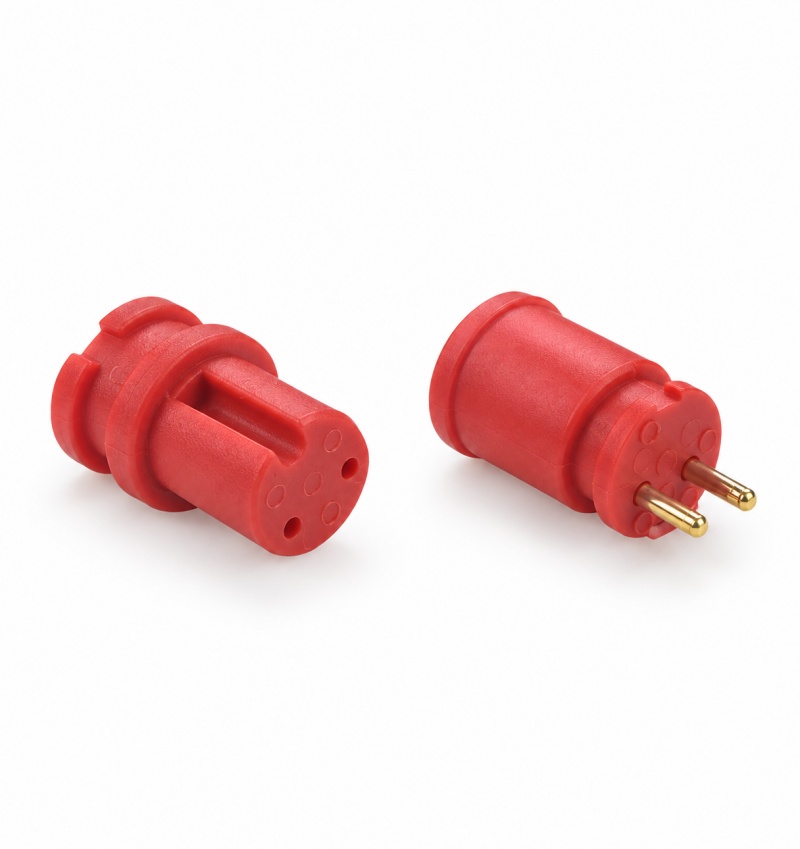
The connector features a red outer body with a smooth cylindrical surface and raised molded sections. The front portion is shaped around the contact interface, while the wider rear housing forms the main connector body.
The female component has two visible openings on its front face. The male component carries two metallic pins that extend outward from the housing.
Both parts share a similar exterior profile, allowing them to function as a corresponding connector pair when their dimensions and contact positions are compatible.
A two-pin connector is commonly selected when a circuit requires only two separate conductive paths. The M7-2P provides this configuration through a pair of metal contacts.
Depending on the equipment design, the two positions may be assigned to positive and negative conductors or other electrical functions.
The contact layout should be identified before wiring. Pin numbering and polarity must follow the relevant product drawing to prevent reversed connections.
Integrating the M7-2P connector into a cable assembly requires attention to the conductor size, termination method, and available mounting space.
The cable connection method should be confirmed from the technical specification rather than determined from the external housing appearance.
During assembly, the following points should be checked:
Correspondence between male and female contact positions.
Correct assignment of the two electrical conductors.
Compatibility between the connector terminals and the selected cable.
Sufficient clearance around the connector body.
Proper contact engagement after mating.
The M7-2P can be evaluated for electrical products that need a detachable connection with two contact positions.
Equipment Power Interfaces
For compatible low-power equipment, the connector may serve as a two-conductor interface when its rated current and voltage meet the circuit requirements.
Electronic Control Assemblies
Devices with simple two-wire connection requirements may use this type of connector to join separate wiring sections.
Modular Electrical Components
A male and female connector pair can provide a removable connection between compatible electrical modules.
Custom Equipment Wiring
The M7-2P may also be considered in specialized wiring assemblies where the required connector dimensions and contact arrangement match the equipment design.
The M7-2P designation identifies the connector model and its two-contact configuration. Exact measurements and electrical performance depend on the manufacturer's corresponding specification.
Before selecting this connector, confirm the following technical information:
Overall connector dimensions
Contact spacing and pin diameter
Rated operating voltage
Maximum rated current
Contact and insulation materials
Cable termination method
Operating temperature range
Environmental protection rating
These details are necessary when evaluating the connector for a particular electrical application.
Before mating the connector, inspect the pins and socket openings for deformation or foreign material. The two contact positions should be aligned correctly before engagement.
Do not force the male component into an incompatible socket, as this may bend the pins or damage the contact surfaces.
The electrical circuit should be disconnected before installation or removal unless the connector has been specifically rated for connection under load.
For installations involving movement or vibration, the suitability of the connector retention structure should be confirmed using the applicable product specification.
Q1: How many electrical contacts does the M7-2P connector have?
The M7-2P has two contact positions, consisting of two metal pins on the male connector and two corresponding sockets on the female connector.
Q2: What color is the connector housing?
The connector has a red molded housing on both male and female components.
Q3: Can the male and female parts be ordered separately?
The image shows both connector types. Individual or paired supply options depend on the available ordering configurations.
Q4: Does the connector have a locking mechanism?
The visible housing includes molded structural features, but the exact retention or locking method should be confirmed from the product drawing.
Q5: Is this connector suitable for a two-wire circuit?
Yes, the two-contact arrangement can be used for compatible two-wire circuit designs, provided the electrical ratings and wiring requirements are satisfied.
Q6: How can I confirm whether this connector fits my equipment?
Compare the connector's mating dimensions, contact positions, termination structure, and electrical specifications with the equipment requirements.
Q7: What should be checked before installation?
Verify the wiring polarity, pin alignment, electrical rating, cable compatibility, and mating condition before connecting the equipment.
 RELATED
 RELATED


Copyright © 2026 All rights reserved Sitemap
Technical Support:hzw
This website uses cookies to ensure you get the best experience on our website.


 WhatsApp
 Phone
Phone