

Bottom line up front: an M12 D-Code Shielded Molded Cable is the factory-floor replacement for the fragile office-grade RJ45 patch cord. With four shielded contacts arranged in the D-coded keying pattern, a Cat5e-grade twisted-pair core, and a molded overmold that seals the connector to IP67 or better, it carries 100 Mbps Fast Ethernet — the physical layer used by PROFINET, EtherNet/IP, Modbus TCP and EtherCAT segments — into wash-down, oily, vibrating and electromagnetic-hostile environments where a plastic RJ45 plug would fail within weeks. This guide explains how D-coding differs from A-, B- and X-coding, how to read the pinout correctly, which jacket material survives your application, how to budget cable length and bend radius, and how to specify a cordset that your production line will not have to revisit for years.
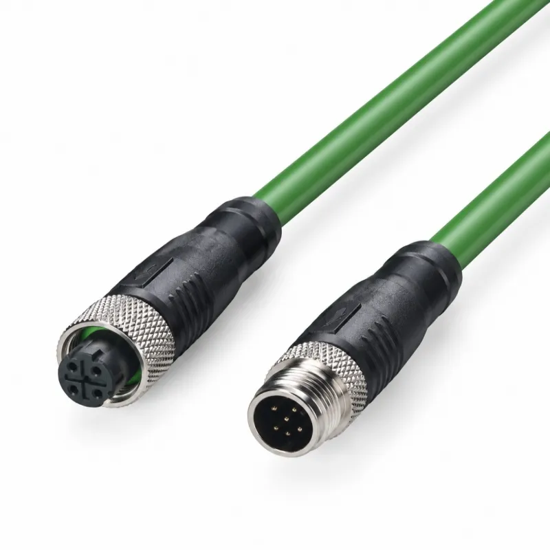
An M12 D-Code shielded molded cable — often called a D-coded M12 cordset — is a circular connector cable assembly with three defining characteristics. First, the connector follows the M12 form factor: a 12 mm threaded circular shell standardized in IEC 61076-2-101, with a metric M12×1 coupling thread that screws down onto the mating receptacle for a vibration-proof, sealed connection. Second, the insert inside the shell carries exactly four gold-plated contacts arranged in the D-coded key geometry, whose offset keyway physically prevents the connector from being mated with A-coded sensors, B-coded fieldbus drops or X-coded 10G ports. Third, the cable is terminated by overmolding: the factory injects a polymer boot directly around the contact carrier and the cable jacket, fusing connector, shield and cable into a single homogeneous, watertight unit.
The word shielded matters as much as D-Code. Industrial Ethernet installations live next to variable-frequency drives, contactor coils, servo cables and welders. An unshielded cordset would act as an antenna, collecting common-mode noise and re-radiating it into the receiver. A proper D-code cordset terminates the overall foil-and-braid shield of the cable 360 degrees to the metal coupling nut, so that noise currents flow through the shell and into the chassis of the device rather than onto the data pairs. When you compare quotations between suppliers, the quality of that 360-degree shield termination is one of the biggest invisible differentiators — and one of the hardest to retrofit after a line is commissioned.

The M12 family assigns letter codes to prevent electrical and mechanical mismating between incompatible signal types. Understanding where D-coding sits helps you future-proof a machine design and avoid expensive connector confusion during maintenance.
| Code | Typical pins | Typical signal | Data class | Typical use |
|---|---|---|---|---|
| A-Code | 2–17 | 24 V sensor/actuator power, analog signals | DC / low-frequency | Proximity switches, I/O blocks, solenoid valves |
| B-Code | 4, 5 | Fieldbus (PROFIBUS-style) data | 12 Mbit/s fieldbus | Legacy fieldbus drops, interbus segments |
| D-Code | 4 | Fast Ethernet, two twisted pairs | 100 Mbit/s | PROFINET, EtherNet/IP, Modbus TCP, EtherCAT |
| X-Code | 8 | Gigabit/10G Ethernet, four twisted pairs | 1–10 Gbit/s | Machine vision, high-speed aggregation links |
Because A-, B-, D- and X-coded inserts use different keyway offsets, a D-coded plug cannot physically enter an A-coded receptacle. This is a deliberate design: an engineer who accidentally plugs a 24 V sensor cable into an Ethernet port — or the reverse — would otherwise destroy I/O electronics. When you standardize a machine on D-coded M12 for all 100 Mbps links, the coding system itself becomes part of your error-proofing (poka-yoke) strategy.
One practical caution: never file down a keyway to force a mismatched connection. The keying also protects the impedance profile of the link. A D-coded insert mated to a modified X-coded port will ruin return-loss performance and produce intermittent errors that are miserable to diagnose.
The D-coded insert carries four contacts that map to the two data pairs of 100BASE-TX Fast Ethernet. The canonical assignment is:
| M12 pin | Signal | Pair | Conductor color (typical T568B-style cord) |
|---|---|---|---|
| 1 | TD+ (transmit data +) | Pair 1 | White/Orange |
| 2 | RD+ (receive data +) | Pair 2 | White/Green |
| 3 | TD− (transmit data −) | Pair 1 | Orange |
| 4 | RD− (receive data −) | Pair 2 | Green |
Three reading rules prevent the most common wiring mistakes:
Pin numbers flip between genders. Pin numbering is defined looking at the male face (the side with pins). The same conductor occupies a different printed position when you look at the female side. Always trace continuity with the supplier's wiring chart rather than by sight.
Trust the pair, not the color. Cable stocks vary between IEC 60708-style color codes, T568B-style codes and manufacturer-proprietary schemes. What matters electrically is that TD+ and TD− land on the same twisted pair, and RD+ and RD− on the other. Splitting a pair across two different twists destroys noise rejection even though a continuity tester will happily report "good".
Shield to shell, one end preference. For grounded networks, terminate the drain and braid 360° to the connector shell at both molded ends, and let the device chassis bond the shield to protective earth. Avoid daisy-chaining shield bonds through painted surfaces — paint is an insulator.
If you are terminating an M12-to-RJ45 version (common at the cabinet boundary, where the cordset enters a standard switch), the RJ45 side uses the familiar 8P8C positions 1, 2, 3 and 6; positions 4, 5, 7 and 8 remain unconnected for a four-wire Cat5e cord.
The table below summarizes the electrical envelope of a typical shielded D-code molded cordset. Individual catalog items vary — always confirm against the datasheet of the exact part number — but these figures describe the mainstream industrial offering.
| Parameter | Typical value | Notes |
|---|---|---|
| Data rate | 100 Mbit/s | 100BASE-TX Fast Ethernet physical layer |
| Cable category | Cat5e | Per ISO/IEC 11801 channel practice; connectors per IEC 61076-2-101 |
| Contacts | 4 | Two twisted pairs, gold plating over nickel |
| Rated current | ≤ 4 A per contact | Signal-level rating; not intended for device power delivery |
| Rated voltage | 30–60 V | Depends on insert and manufacturer series |
| Characteristic impedance | 100 Ω differential | Must be maintained through connector, mold and cable |
| Shield construction | Foil + braid (SF/UTP) | 360° termination to coupling nut |
| Ingress protection | IP67 (mated) | IP68/IP69K available on premium series |
| Operating temperature | −25 °C…+80 °C (PVC) / −40 °C…+80 °C (PUR) | Cold-flex PUR compounds extend the low end |
| Mating cycles | ≥ 100 typical | Gold-plated contacts hold contact resistance low across cycles |
Note what the D-code is not: it is not a power connector. Attempting to feed meaningful current through the data pairs — for example to power a remote device over Ethernet without a proper power standard — is outside the design envelope. If you need power and data in one M12 thread diameter, look at L-coded or Y-coded variants instead, or keep data and power cordsets separate.
Not every cable labeled "shielded" delivers the same noise immunity. In a D-code molded cordset, shielding is a chain of five elements, and the link is only as good as its weakest joint:
Cable shield: an aluminum-polyester foil wrapped around the pairs (provides 100% coverage against high-frequency fields) plus, in SF/UTP constructions, an overlaid tinned-copper braid (provides low-frequency conductivity and mechanical strength).
Drain wire: a bare conductor running along the foil so that terminating the foil does not require unwrapping it in the field — irrelevant once the cable is overmolded, but a good indicator of the cable stock's quality.
Overmold shield clamp: inside the molded boot, the braid is clamped around the full circumference (360°) onto a metal ferrule or the coupling nut itself. A "pigtail" termination — where the braid is gathered into a wire and soldered to one point — surrenders 20–30 dB of high-frequency shielding performance and should be rejected in OEM specifications.
Coupling nut continuity: the nickel-plated brass nut mates with the receptacle shell, bonding shield to chassis through the threaded joint. Check that receptacles are mounted to unpainted, conductive surfaces or use grounding washers.
Cable-to-boot strain relief: the overmold must grip the cable jacket, not the braid. If the braid carries mechanical load, the foil works loose and shield continuity drifts with every flex cycle.
When evaluating samples from a new supplier, a four-point test catches most defects: measure shield continuity end-to-end (should be well under 1 Ω), measure conductor-to-shield insulation (should be in the hundreds of megohms), flex the cordset 90° ten times at the boot and re-measure continuity, and finally run a real 100 Mbps link with an Ethernet tester while a nearby motor starter cycles. The last test — noise under real switching load — is the one that laboratory specifications most often fail to predict.
The overmold boot is usually the same polymer family as the cable jacket, so choosing the jacket material is really choosing the environment the whole cordset will tolerate.
| Property | PVC | PUR | TPE |
|---|---|---|---|
| Oil resistance | Moderate | Excellent | Very good |
| Abrasion resistance | Fair | Excellent | Good |
| UV / outdoor | Poor–moderate | Good | Good |
| Flex life (drag chain) | Poor | Excellent (millions of cycles) | Very good |
| Low-temperature flex | Stiff below −10 °C | Flexible to −40 °C | Flexible to −40 °C |
| Weld-slag resistance | Poor | Good | Moderate |
| Cost | Lowest | Highest | Mid |
Rules of thumb: indoor cabinets and fixed machine wiring tolerate PVC; anything on a robot arm, drag chain, or near cutting fluid wants PUR; food-washdown and cold-storage environments benefit from TPE compounds certified for the relevant hygiene and temperature ranges. If your application involves both oil and continuous motion, PUR with a fine-strand (Class 6) conductor is the safe default — and it is the combination used in the vast majority of PROFINET cordsets shipped into automotive and packaging plants.
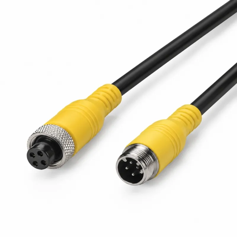
M12 D-code connectors exist in two families: field-terminable connectors that a technician assembles on site, and factory-molded cordsets. Each has a legitimate place, and knowing the boundary prevents both over-spending and under-engineering.
Choose molded cordsets when: the length is known at design time; the link carries production-critical traffic; the environment is wet, oily or washed down; the installation will be repeated across many identical machines (serialized quality control matters); or technicians at the site are not trained in shield termination. Overmolding gives repeatable 360° shielding, guaranteed IP67, controlled strip geometry, and per-piece electrical test records — advantages a field termination cannot match at any labor rate.
Choose field-terminable when: lengths are unpredictable at commissioning; the drop is inside a sealed IP54 cabinet where ingress protection is irrelevant; or the connection is temporary. Field connectors also shine for spare-parts logistics: one reel of cable plus a box of connectors covers every conceivable length.
The hidden cost of field termination is variance. Two technicians terminating the same connector can produce link margins that differ by 6–10 dB in return loss. On a margin-starved 100-meter channel that difference is the difference between a clean production acceptance test and a week of intermittent-error hunting. For trunk and drop cables outside cabinets, the industry has clearly voted: molded cordsets dominate new machine builds.
A 100BASE-TX channel over Cat5e is specified up to 100 meters between active ports, but industrial practice budgets more conservatively because cordsets add connector pairs, and factory temperatures shift attenuation. A workable budget for a PROFINET-class link:
Fixed installation Cat5e trunk: up to 90 m, leaving 10 m for two patch or cordset ends.
Two molded D-code cordsets plus an in-line coupler: keep the total under 70 m; every additional connector pair consumes margin.
Continuous-flex PUR cordsets on moving axes: treat 30–50 m as the practical ceiling and verify with an on-site link test, because flex-grade cable trades attenuation margin for mechanical life.
Beyond 100 m: insert a switch. Do not stretch the channel; the failure mode is not "no link" but intermittent collisions and retries that degrade the whole network segment.
Remember also what D-code cannot do: 1000BASE-T and 2.5/5/10GBASE-T require four pairs and an X-coded insert. If a machine roadmap includes Gigabit machine vision or 10G aggregation, run X-coded cabling from the start for those links while standardizing D-code for the 100 Mbps device layer. The two code types cannot be cross-mated, so mixed plants remain mistake-proof.
Because the D-code cordset implements the standard 100BASE-TX physical layer, it is protocol-agnostic at the cable level — any industrial Ethernet protocol that rides Fast Ethernet works. The practical differences appear in conformance and diagnostic requirements:
PROFINET: conformance classes define cabling quality expectations; Class A and B operate happily at 100 Mbps over D-coded cabling. Installers familiar with the guideline know the two-pair/four-pair distinction: a four-wire cordset suffices for 100 Mbps-class service.
EtherNet/IP: device-level ring topologies (DLR) use the same physical layer; ensure every ring member's ports are 100 Mbps-capable and that cordsets are of consistent, tested quality, because ring recovery time assumes deterministic link behavior.
EtherCAT: cycle times at 100 μs and below punish any marginal link. Use molded cordsets with verified return loss, avoid couplers in EtherCAT chains, and keep each segment within the length budget above.
Modbus TCP and general SCADA telemetry: tolerant of modest margins, but the same discipline prevents nuisance timeouts on long polling intervals.
One integration note: some devices auto-negotiate while others are fixed at 100 Mbps full-duplex. A cordset is transparent to negotiation, but damaged pairs can force a 10 Mbps half-duplex fallback that halves throughput and wrecks determinism. If a link quietly negotiates down, inspect the cordset before blaming the switch.
Use this checklist to convert an application description into an orderable part number without iteration:
Gender and orientation: male (pins) or female (sockets); straight or angled (90° and 270° angled boots solve clearance problems at tight machine walls).
Termination on the far end: open-ended pigtails into terminal blocks, second M12 D-code (device-to-device trunk), or RJ45 for the cabinet boundary.
Pole count: 4-pole for Fast Ethernet. Do not order 8-pole X-code "to be safe" — it will not mate with D-coded receptacles.
Jacket material: PVC for fixed indoor, PUR for oil/flex/washdown, TPE for cold or hygiene-regulated areas.
Conductor gauge and pairs: 26 AWG (7×0.34 mm typical) 2-pair is standard; 22 AWG for longer channels or higher mechanical robustness.
Length: standard catalog lengths 0.3/0.5/1/2/3/5/7.5/10/15/20 m cover most layouts; confirm the length budget of Section 8.
Ingress and temperature rating: IP67 minimum mated; IP68/IP69K for high-pressure washdown; confirm temperature range against ambient extremes including sunlight load.
Flex class: if the cordset moves, specify drag-chain-rated construction with a stated flex-cycle figure, not merely "flexible".
Shielding detail: require 360° shield termination in the drawing or datasheet, not just the word "shielded".
Compliance documents: RoHS/REACH declarations, and where relevant UL/CSA style or CE marking for the finished cordset rather than only the connector.
Suppliers who can answer every line of this list from their standard datasheet — and who mold their own connectors rather than reselling — are generally the ones who can also support the customization requests that come later in a machine program.
A high-quality cordset can be installed badly enough to forfeit its advantages. Five practices preserve the design margin:
Respect bend radius: 5× cable outer diameter when fixed, 10× where the cable flexes. The zone immediately behind the molded boot counts — clamp the cable so that bending happens along the run, not at the boot edge.
Separate from power: maintain at least 20–30 cm from VFD motor cables; cross high-voltage runs at 90° when crossing is unavoidable. Trays with dividers pay for themselves in reduced diagnostics.
Ground at the chassis, not through the cable: bond shields via device housings and mounting plates. Avoid shield-to-ground loops by bonding at one deliberate point per segment when noise analysis indicates circulating currents.
Strain-relieve, do not pinch: P-clamps should hold the jacket with slight compliance. Over-tightened clamps cold-flow the jacket and eventually expose the braid.
Label and torque: mark both cordset ends with the circuit ID and torque the coupling nuts to the datasheet value (typically 0.4–0.6 N·m for M12). Hand-tight "snug" is the most common commissioning shortcut and the most common source of intermittent contact in vibrating equipment.

Field experience across packaging, automotive and logistics installations shows that most D-code cordset failures cluster into a small set of patterns:
| Symptom | Likely cause | Confirm by | Fix |
|---|---|---|---|
| Link negotiates to 10 Mbps half-duplex | One pair damaged (often at boot edge) | Pair-length test with Ethernet certifier | Replace cordset; add strain relief |
| Intermittent drops near door of panel | Coupling nut not torqued; vibration | Wiggle test while pinging | Torque to spec; apply thread variant with lock feature if needed |
| Errors rise when a large motor starts | Shield termination quality; routing too close to motor cable | Ferroscope or scope on common-mode; inspect boot clamp | Re-route, re-terminate, or substitute cordset with verified 360° clamp |
| Corrosion at mating face after washdown | Connector mated unmated; worn thread seal | Visual; IP test | Replace with IP69K series; use protective caps on unmated ports |
| Boot cracks in cold store | PVC used below its rating | Temperature record of zone | Switch to low-temperature PUR/TPE compound |
| Foil shield pulled loose inside boot | Braid carrying mechanical load | Tug-test sample; continuity drift after flexing | Cordset with jacket-anchored strain relief; re-clamp run |
A cheap handheld Ethernet certifier that reports pair lengths and margin is, along with a torque screwdriver, the highest-return tool a maintenance team can own for this failure class.
Standard catalog cordsets cover mainstream needs, but machine builders routinely customize three or four parameters — and a factory that molds its own connectors can support this economically at moderate volumes:
Hybrid lengths and label schemes: exact lengths in 0.1 m increments, printed circuit IDs, color-coded boots or heat-shrink labels that match the machine's electrical documentation.
Jacket and boot combinations: for example a PUR cable stock with an angled boot to clear a guard, or a flame-retardant compound for a rail or marine specification.
Pigtail terminations: open-ended cords with pre-stripped, tinned conductors and pre-installed ferrules, ready for direct landing on I/O terminals.
Custom packaging and kitting: per-machine kits bagged and labeled so that a single part number on the BOM expands into a complete cable set at the assembly station.
The engineering conversation to have with a supplier before committing is simple: ask for the mold library (which boot geometries and thread types exist as existing tooling), the minimum order quantity for a new boot color, and the sample lead time. Factories that own their molding process answer in days; resellers answer in weeks.
Because a molded cordset hides its interior workmanship, process control at the factory is the buyer's only assurance. A serious production flow includes:
Incoming cable inspection: jacket concentricity, conductor resistance per IEC batch sampling, and shield coverage verification.
Crimp/solder control on contact attachment: pull-force sampling and cross-section checks on the contact-to-conductor joint.
Molding process windows: documented temperature, pressure and cycle parameters per polymer, with first-article and last-article dimensional checks per shift.
100% electrical test: continuity, conductor-to-conductor and conductor-to-shield hipot, plus shield continuity — every cordset, not a sample.
Dimensional and visual audit: thread gauges on coupling nuts, boot geometry against drawing, and surface-finish criteria for the sealing faces.
Environmental sampling: periodic IP67 dunk tests on mated samples and thermal-cycling of boots to catch compound drift.
When auditing a potential supplier, ask to see the 100% test station and its record trail: the ability to retrieve the test result for a specific cordset serial number months later is a stronger quality signal than any certificate framed on the wall.

No. The keyways are intentionally incompatible. The coding exists to protect both the electronics and the impedance design of the link; forcing a connection voids both.
For 100BASE-TX (PROFINET, EtherNet/IP and EtherCAT at the device level), Cat5e two-pair shielded cable is the reference medium and is specified for exactly this service. Gigabit and faster links are where four-pair Cat6A X-coded cabling takes over.
Fixed runs tolerate 5× outer diameter; flexing runs need 10×. The critical spot is the first 20–30 mm behind the molded boot, which should be clamped so that bending happens in the cable, not at the boot edge.
In typical industrial Ethernet practice the shield is continuous through both molded ends and bonds to chassis ground through each device's connector port. The devices themselves provide the ground reference. Avoid adding random pigtail grounds along the run, which create loops that radiate noise.
D-code is a 4-pole, Cat5e-class connector for 100 Mbps Fast Ethernet; X-code is an 8-pole, Cat6A-class connector for 1–10 Gbit/s Ethernet — and their keyways prevent them ever being swapped.
Yes, if the jacket is UV-stabilized (PUR grades generally are) and the mated connection meets the required ingress rating. For permanent outdoor runs, also confirm the operating temperature range includes the installation's worst-case sun-load temperature.
Sample-check continuity and shield end-to-end resistance, confirm thread gauge fit on a known-good receptacle, run a 100 Mbps link test with a certifier on a few random pieces, and review the factory's 100% electrical test documentation for the batch.
The M12 D-Code shielded molded cable succeeds because it industrializes a consumer connector concept: it takes the two-pair simplicity of Fast Ethernet, wraps it in a keyed, threaded, sealed metal shell, and fuses it to shielded Cat5e cable with a molding process that no field technician can replicate. Specified with the checklist in Section 10, installed with the discipline of Section 11, and sourced from a factory that molds and 100% tests its own assemblies, a D-code cordset becomes one of the least-eventful components on a machine — which is exactly what a network infrastructure component should be. When your next machine program needs 100 Mbps links that survive washdown, oil mist, vibration and years of duty cycles, the D-coded M12 cordset remains the shortest path between a reliable design and a quiet production floor.


Copyright © 2026 All rights reserved Sitemap
Technical Support:hzw
This website uses cookies to ensure you get the best experience on our website.


 WhatsApp
 Phone
Phone
Comment
(0)