

M12 X-Code Shielded Molded Cable assemblies have become the default physical layer for 10-gigabit industrial Ethernet in factories, machine vision cells, rail vehicles and outdoor infrastructure. Unlike the A-coded and D-coded M12 variants that dominate sensor wiring, the X-coded version packs eight contacts into a cross-shaped shield arrangement inside the same 12 mm threaded shell, which is exactly what makes 10GBASE-T possible in a circular, watertight connector. This guide explains how the X-coded interface works, what actually determines signal integrity at 10 Gbit/s, how molded assemblies differ from field-wireable plugs, and how to specify, install and test a cable that survives washdown, vibration and years of continuous flexing.
An M12 X-Code shielded molded cable is a factory-terminated Ethernet cable assembly that combines three elements: an M12 connector with X-coding on one or both ends, a Cat6A-class shielded twisted-pair cable, and a moulded strain relief that fuses the connector shell, the cable jacket and the sealing geometry into one continuous, watertight body.
Each part of that description carries meaning, and it helps to unpack them one by one.
The M12 interface. The M12 is a circular connector with a 12 mm metric locking thread. It was originally standardised for industrial sensors because a threaded metal coupling resists vibration far better than a snap-in RJ45 latch, and because the sealing ring around the mating face allows the pair to reach IP67 or even IP68 when the connector is properly tightened. Today the same interface carries power, signals and Ethernet across automation, transportation, marine and energy installations.
X-coding. Inside the circular shell, the contact insert determines what the connector can do. X-coding arranges eight gold-plated contacts in a cross-shaped pattern, with four individually shielded twisted pairs. That cross-shaped shield is not cosmetic; it is the mechanical reason why four high-frequency pairs can coexist inside a 12 mm body without crosstalk destroying the signal.
Shielding. A shielded assembly uses a shielded cable (typically S/FTP construction with an overall braid plus foil around each pair) and a metal connector shell that terminates the shield continuously across the joint. The shield is only useful if it is electrically continuous from the cable screen, through the 360-degree termination inside the backshell, to the metal housing of the device at the other end.
Molded. A molded cable is overmoulded: molten PVC or PUR is injected around the connector rear and the first section of cable, forming a monolithic strain relief. This is what distinguishes a molded assembly from a field-assembled or field-wireable connector, where the boot is slid over the cable rather than fused to it.

Industrial Ethernet grew up at 10 and 100 Mbit/s, and the M12 coding scheme grew with it. Understanding why only X-coding reaches 10 Gbit/s requires a quick look at how each coding arranges its contacts.
A-code is the general-purpose sensor coding. It is defined with 2, 3, 4, 5, 6, 8, 9 and 12 contact positions and is used for power, discrete signals, DC supplies and PROFINET device ports. Its contact geometry is optimised for low-frequency signals, not for a 500 MHz channel.
B-code exists with 12 contacts in a specific keying for Fieldbus and Profibus installations.
D-code uses four contacts arranged as two pairs. It was the first M12 coding designed for data and carries 100 Mbit/s Fast Ethernet and PROFINET RT reliably. Because only two pairs are present, the physical ceiling is one gigabit in carefully engineered short runs, but D-code was never intended for 10GBASE-T.
X-code uses eight contacts arranged as four pairs, matching the four-pair structure that 1000BASE-T and 10GBASE-T require, and adds shielding between the pairs themselves.
The decisive difference is the internal shield. In an X-coded connector, a cross-shaped metal divider sits between the four pairs inside the insert. Without that divider, the pairs would couple into one another; the phenomenon engineers call alien crosstalk would push bit errors far beyond what the receiver can correct at 10 gigabit speeds. The X-shaped insert therefore performs two jobs at once: it provides the unique keying that prevents an X-coded plug from being mated with an A- or D-coded receptacle, and it acts as an internal shielding partition.
This is also why an X-coded cable cannot simply be "upgraded" by re-pinning an A-coded connector. The shell diameter is the same 12 mm, but the insert, the contact layout and the shielding concept are entirely different. Intermateability between X-coding and every other M12 coding is deliberately excluded by the standard.
A 10-gigabit rated molded assembly is only as good as its weakest element. When evaluating a datasheet, these are the construction details that matter.
Cat6A industrial cables for M12 terminations typically use 26 AWG or 24 AWG stranded bare copper conductors. Stranding matters: solid conductors offer lower insertion loss but tolerate almost no flexing, while stranded conductors survive continuous movement in drag chains and robot dress packs at the cost of slightly higher attenuation. The four pairs must be manufactured with controlled twist rates so that differential delay skew stays inside the limits defined for the channel.
The most common construction for a 10G industrial assembly is S/FTP: an overall braided screen plus foil shields around each individual pair. The per-pair foil is what suppresses alien crosstalk between the four pairs, while the overall braid provides a low-impedance path to ground and mechanical protection. A cheaper F/UTP cable (foil only, no braid) can still meet Cat6A on the bench, but in a cabinet full of variable-frequency drives the braid is what keeps transfer impedance low at high frequencies.
PVC is the economical choice for static, indoor routing. PUR (polyurethane) is the industrial default: it resists oils, coolants and abrasion, remains flexible at low temperature, and is halogen-free in many industrial grades. Cable destined for drag chains is additionally specified with a minimum bend radius and a bending-cycle rating, commonly several million cycles for high-flex grades.
The moulded strain relief is the part that turns a cable and a connector into an assembly. A good overmold provides a gradual transition of stiffness so that bending stress is distributed rather than concentrated at the solder points. It also completes the sealing path: the O-ring on the connector face handles the mating interface, while the overmold handles the cable entry. Assemblies rated IP67 are protected against temporary immersion; IP68 variants extend that to continuous or prolonged immersion under defined conditions.
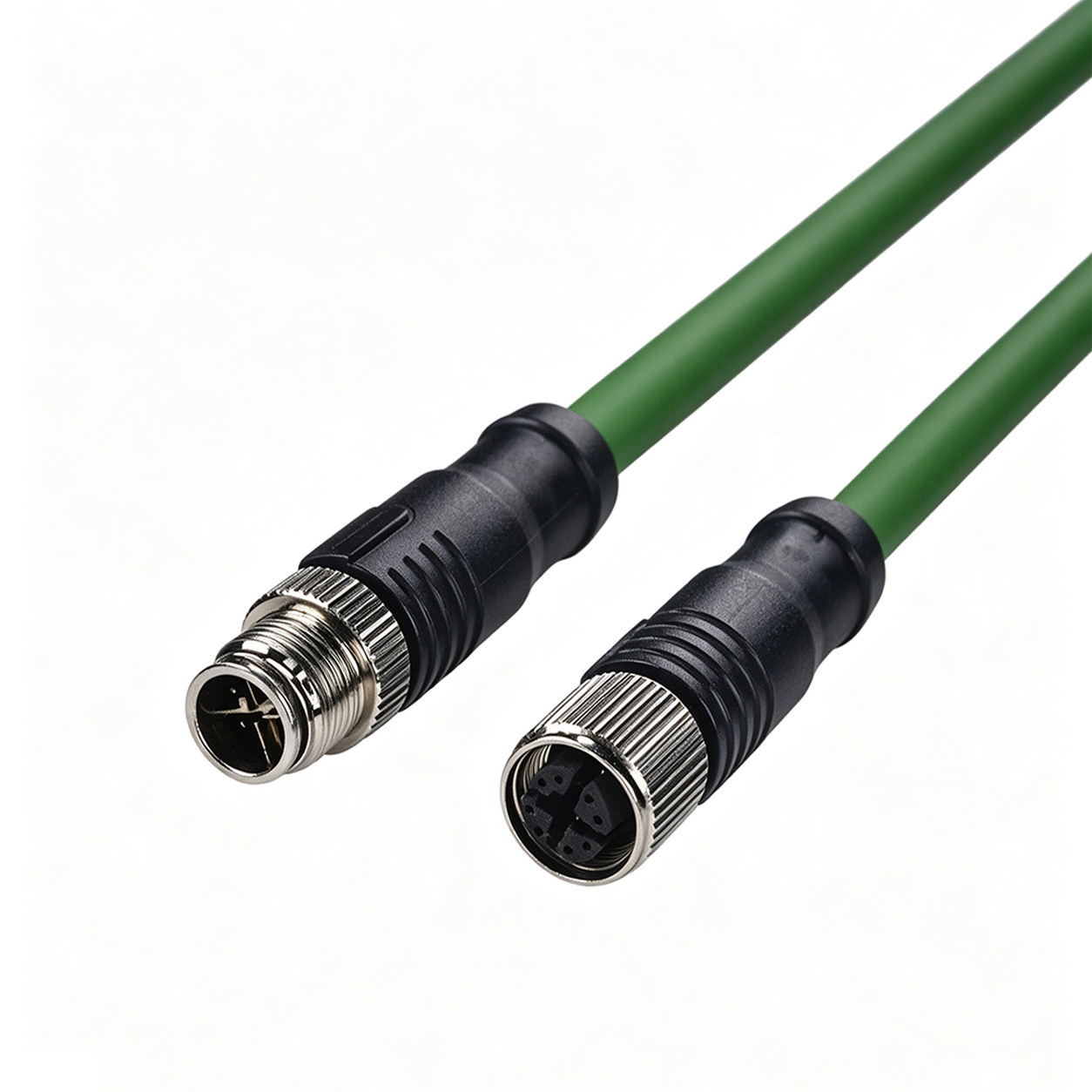
Selecting the wrong coding is the single most common specification error with M12 Ethernet hardware. The table below summarises the practical differences.
| Characteristic | A-Code | D-Code | X-Code |
|---|---|---|---|
| Contact arrangement | 2–12 poles, general purpose | 4 poles, 2 pairs | 8 poles, 4 pairs |
| Primary use | Sensors, actuators, DC power, PROFINET device ports | 100 Mbit/s Ethernet, PROFINET RT | 10GBASE-T, 10 Gigabit Ethernet |
| Data bandwidth | Not intended for data | 100 Mbit/s standard | 10 Gbit/s over Cat6A |
| Internal pair shielding | No | No | Yes, cross-shaped shield |
| Governing standard | IEC 61076-2-101 family | IEC 61076-2-101 (D variants) | IEC 61076-2-109 |
| Mates with other codings | No | No | No |
Two practical consequences follow from this table. First, an X-coded plug physically cannot be inserted into a D-coded receptacle, which is a useful guard against mis-wiring in the field. Second, if a machine's service port is D-coded, an X-coded cable will not help; the device end defines the ceiling regardless of how good the cable is.
Cat6A is a channel specification, not a cable specification. That distinction has real consequences for M12 assemblies.
The channel defined by ISO/IEC 11801 and the TIA standards includes the cable, the connectors at both ends and the patching in between. When a manufacturer claims a Cat6A assembly, the claim is that this specific combination of cable and connector maintains return loss, insertion loss, near-end crosstalk, far-end crosstalk and delay skew within the limits of the class across the rated frequency range, which for Cat6A extends to 500 MHz.
Two factors dominate how much of that margin survives in a real installation.
Length. Channel margin is finite, and the connectors consume a disproportionate share of it. Short machine-mounted runs of a few metres comfortably meet the class. Very long runs approaching the 100 metre channel limit leave little room for anything other than an ideal termination, and at that point a fibre hybrid or a media conversion becomes the more robust engineering choice.
Termination quality. In a molded assembly the termination is made once, under factory conditions, with calibrated tooling and verified pinout. That is a significant advantage over field terminations, where pair untwist at the contact point is the main source of crosstalk degradation and is difficult to control without practice and the right jig.
A shielded cable installed badly performs worse than an unshielded cable installed well, because a floating or intermittently bonded screen becomes an antenna. Three points deserve attention.
The screen must be continuous from end to end. In a molded assembly this is handled by the 360-degree termination inside the connector backshell, where the braid is clamped around the full circumference rather than gathered into a pigtail. A pigtail termination adds inductance and destroys shield effectiveness at the frequencies where it matters.
The shield needs a defined reference. In most industrial installations the shield is bonded at both ends, which gives the lowest transfer impedance, provided the grounding system between the two ends is sound. Where a ground potential difference exists between cabinets, engineers sometimes bond at one end only to avoid circulating currents; that decision should be made deliberately as part of the EMC plan, not discovered after the fact.
Shielding reduces coupling, it does not eliminate it. Routing an Ethernet cable in the same tray as motor feeder cables, directly alongside a drive output, or across the cable of an unmaintained switching power supply will inject noise that no cable construction can fully reject. Separation distances and the use of grounded steel trays are still part of the design.

Field-wireable M12 connectors have their place: they allow a cable to be cut to length on site, they suit retrofit work, and they are indispensable when a connector must pass through a small opening. For permanent 10-gigabit infrastructure in a demanding environment, however, molded assemblies are usually the better engineering choice.
Repeatable electrical performance. Factory tooling controls pair untwist, contact crimp and shield termination identically on every unit. Field assembly quality varies with the technician, the tool and the time available.
Sealing integrity. The overmold forms a continuous barrier at the cable entry. Field-assembled boots rely on compression and adhesive, which is adequate for IP65 and often acceptable at IP67, but harder to guarantee at IP68 or in washdown areas.
Strain relief. A moulded transition distributes flexing stress over a length of cable rather than concentrating it at the contact tips, which is why molded assemblies survive drag-chain and robotic duty far longer.
Traceability. Every molded assembly can be tested and serialised before it ships. A field termination is only verified after it is installed, when diagnosing a problem is already expensive.
Datasheets vary in quality. Before committing to a supplier, confirm that the following items are stated explicitly rather than implied.
| Parameter | Typical value for a 10G industrial assembly |
|---|---|
| Connector coding | M12 X-coded, 8-pin, male or female, IEC 61076-2-109 |
| Ends | M12 to M12, or M12 to RJ45, straight or angled |
| Cable category | Cat6A S/FTP, 4 × 2 × 26 or 24 AWG stranded |
| Characteristic impedance | 100 ± 15 ohm nominal |
| Transmission class | 10GBASE-T capable, 500 MHz |
| Rated current / voltage | 0.5 A per contact, 60 V DC typical for data contacts |
| Ingress protection | IP67 mated; IP68 for washdown and outdoor variants |
| Jacket material | PUR or halogen-free industrial PVC |
| Temperature range | Approximately −40 °C to +85 °C, depending on jacket |
| Flex rating | Static, or drag-chain with a stated bend radius and cycle count |
| Shield termination | 360-degree circumferential clamp at both ends |
| PoE support | IEEE 802.3af/at/bt where the system requires it |
One additional question is worth asking any supplier: is the assembly measured as a complete channel against the class, or only as a component? The distinction determines whether the stated performance is a verified characteristic of the assembly or an inference from the cable alone.
The X-coded interface appears wherever three requirements intersect: high bandwidth, a sealed circular connection and mechanical robustness.
Machine vision and inspection. Modern industrial cameras push multi-gigabit image data, and 10GigE vision systems use X-coded links end to end. The sealed interface matters because vision cells are frequently washed down in food, pharmaceutical and packaging plants.
Factory automation backbones. PROFINET, EtherCAT and EtherNet/IP installations route their high-speed segments over X-coded cabling between cabinets, while D-coded links remain on the device level. The X-coded backbone is what keeps cycle times stable when the cell grows.
Rail and rolling stock. Onboard networks, passenger information systems and CCTV backhauls use M12 interfaces for their vibration resistance. Rail applications additionally demand fire behaviour and smoke density compliance, which is a separate specification layer on the cable.
Outdoor and infrastructure. Surveillance cameras, traffic systems, antenna mounts and renewable energy installations use X-coded assemblies where condensation, dust and temperature cycling would defeat an RJ45 latch. Power over Ethernet on the same four pairs simplifies the installation further, because a single cable then carries both the 10-gigabit link and the device supply.
Marine and offshore. Salt fog and washdown environments favour the metal threaded coupling and the option of stainless or nickel-plated shells with compatible sealing materials.

Before releasing a drawing to a cable assembly manufacturer, work through the following list. Each item corresponds to a decision that is cheap to make on paper and expensive to correct after installation.
Confirm the coding at both device ends. X-coded at one end and D-coded at the other is not an upgrade path; it simply does not mate.
Decide the end combination and orientation. M12 to M12 or M12 to RJ45, straight or right-angle, and which gender on which side.
State the length and the routing environment. Length affects channel margin; whether the run is static or flexing decides the cable construction.
Specify the jacket and temperature range. Oil, coolant, UV, ozone and cleaning agents all constrain the material choice.
Define the ingress protection target. IP67 for splashing and temporary immersion, IP68 for washdown or buried conduits.
Clarify the EMC and bonding plan. Shield bonded at both ends or one end, and whether the trays are grounded steel.
Request the test regime. Pinout and continuity on every unit, plus channel or permanent-link measurement on a sampled or full basis.
Agree labelling and packaging. Serialisation, length marking and reel versus coiled packaging all affect installation speed on site.
Even a correctly specified assembly can be compromised by installation. A few habits prevent most field failures.
Respect the minimum bend radius. For static runs the rule of thumb is roughly ten times the cable diameter; for flexing applications, follow the manufacturer's stated radius for the specific construction. Bending tighter than the rated radius increases insertion loss locally and fatigues the shield.
Avoid tension on the connector. The cable gland or the overmold, not the connector body, should carry any pull. Support the cable before it reaches the plug so that vibration at the panel entry is absorbed by the cable, not by the solder joints.
Keep the mating faces clean and lubricated as specified. A trace of silicone-free O-ring grease is acceptable on many designs; petroleum-based greases can swell the elastomer and destroy the seal. Torque the coupling nut to the manufacturer's value rather than hand-tightening, because an under-tightened M12 is the most common cause of intermittent IP failures.
Test, do not assume. A link light proves very little at 10 gigabit. A proper verification uses a channel or permanent-link adapter set and reports return loss, insertion loss, crosstalk and delay skew against the class. On long or critical runs, measuring the actual assembly after installation converts an assumption into a documented result.

Field experience with 10-gigabit industrial links converges on a short list of recurring problems.
Intermittent connection after installation. Usually an under-torqued coupling nut or a cable that was not strain-relieved at the panel entry. Fixing it costs minutes; not fixing it costs days of unexplained link resets.
Bit errors only at high traffic. Classic crosstalk signature. Causes include over-long runs, field terminations with excessive untwist, or routing parallel to a drive output cable. Re-measure the channel and correct the routing before replacing hardware.
Corrosion at the mating face. Caused by a breached seal, typically from a missing O-ring, a damaged sealing surface or an unmated connector left exposed. Protective caps exist precisely for the second case.
Cable jacket cracking. Cold-temperature operation beyond the jacket rating, or a PVC jacket installed where PUR was required. The failure appears months later as a hard fault at the strain relief.
Shield floating. An assembly whose shield is not bonded at the device end shows noise susceptibility rather than outright failure, which makes it harder to diagnose. Verify bonding as part of commissioning.
Yes. An X-coded assembly is fully backward compatible with 1000BASE-T and lower speeds. It simply carries more capability than a D-coded link needs, which is why many installations standardise on X-coded cabling for future-proofing even where current devices are gigabit.
No. The keying, contact count and insert geometry are different by design, and the standard deliberately prevents cross-mating. A device with a D-coded port requires a D-coded cable regardless of the cable's rating.
The Cat6A channel specification allows up to 100 metres, but the achievable margin depends on the connectors and the installation. Short, factory-terminated runs leave healthy headroom; runs approaching the limit should be measured after installation, and very long or high-interference routes are better served by fibre.
Shielded Cat6A constructions with appropriate conductor sizing support PoE classes up to the higher power levels, provided the temperature rise in the cable bundle is accounted for. Confirm the assembly's current rating and the bundle size when designing high-power PoE.
IP67 indicates protection against dust ingress and temporary immersion. IP68 indicates a higher level of continuous immersion protection, with depth and duration defined by the manufacturer. Washdown, outdoor and buried applications should specify IP68 and verify the manufacturer's stated conditions.
Field-wireable X-coded connectors exist, but achieving repeatable Cat6A performance with them requires skill and proper tooling. For permanent infrastructure and harsh environments, factory-molded assemblies are strongly preferred for their consistency, sealing and strain relief.
A high-flex PUR jacket with a stated bend radius and cycle rating is the standard choice. Confirm the minimum bend radius, the number of cycles and whether the construction is rated for continuous motion rather than only static installation.
Most 10-gigabit industrial projects do not fail on the cable specification; they fail on the gap between what was specified and what was actually delivered. That gap is closed by working with a manufacturer that controls the whole assembly process rather than one that merely resells stock lengths.
A capable connector and cable assembly manufacturer will support OEM and project business with custom lengths, a choice of overmold geometry and colour, specific jacket materials for the target environment, right-angle variants where panel clearance is tight, and full electrical verification of each finished assembly. For a project like a machine vision line or a rail retrofit, the ability to match pinout, length, jacket and labelling to the drawing, and to prove the result with test data, is what turns a component purchase into a dependable infrastructure element.
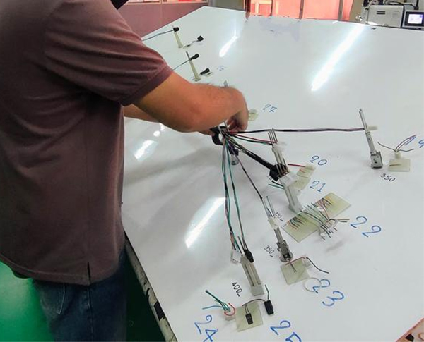
If you are planning a 10-gigabit industrial Ethernet installation and need M12 X-Code shielded molded cable assemblies built to your drawing, the engineering team at XUNPU can review the routing environment, propose the correct jacket and end combination, and supply verified samples before production. Contact us with your project details, cable schedule or drawing package and we will respond with a quotation and lead time.


Copyright © 2026 All rights reserved Sitemap
Technical Support:hzw
This website uses cookies to ensure you get the best experience on our website.


 WhatsApp
 Phone
Phone
Comment
(0)