

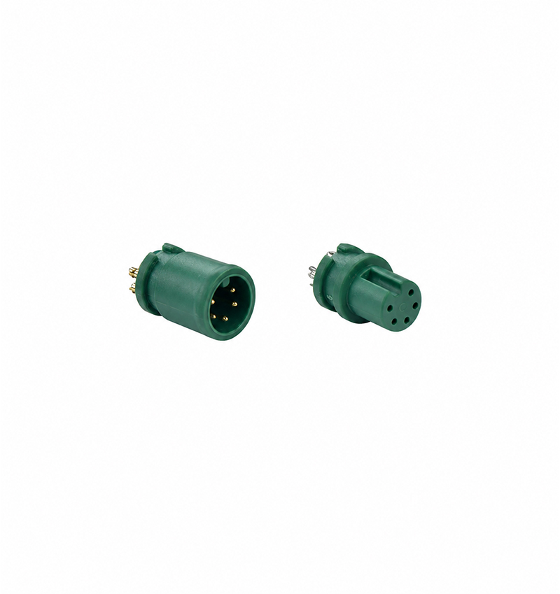
The M6-5P is a circular electrical connector pair with five contact positions housed within a green molded body. The two components have different front-end configurations, allowing the corresponding contacts to engage through a matching circular interface.
The socket-style housing has a recessed opening with visible metal contacts inside. The mating component features a projecting section with five contact openings and a molded guide along the outer surface.
Both components use a compact body design, with a wider section near the rear and smaller mating structures at the front.
The M6-5P provides five independent contact positions within one connector assembly. Each position can be assigned according to the wiring requirements of the connected electrical equipment.
The contacts are grouped inside a circular interface, helping organize multiple conductors without requiring individual connectors for each circuit.
The contact positions must correspond between the two mating components. Before wiring, the terminal identification and circuit assignments should be checked against the connector's technical drawing.
The product has a dark green exterior with a cylindrical molded construction.
The recessed connector body surrounds the internal contacts, while the opposite component has an extended front section with visible contact openings.
Raised sections around the housing form part of the connector's external geometry. A longitudinal molded feature on the projecting component provides a distinct orientation reference.
The housing material, insulation characteristics and temperature resistance should be confirmed from the product specification.
The M6-5P connector has a defined mating shape rather than a completely smooth cylindrical interface.
The projecting connector includes a molded guide feature running along part of its outer surface. The corresponding mating component has an internal geometry intended to accommodate the matching connection structure.
These physical features help establish the correct relative orientation of compatible connector halves.
During assembly, the components should be aligned before engagement. Applying excessive force when the interfaces are incorrectly positioned may damage the contact areas or housing.
Metallic terminals are visible at the rear of the connector components.
These terminals provide connection points between the internal contacts and the external electrical assembly.
The terminal layout should be checked before selecting a mounting or wiring method. Important considerations include terminal spacing, connection orientation and compatibility with the intended assembly process.
The specific termination technique must follow the manufacturer's technical requirements.
The M6 5 Pin Connector can be considered for equipment designs requiring five electrical connection positions.
Multi-Conductor Wiring
The connector combines five separate electrical paths within a single circular interface, providing an organized connection point for compatible wiring configurations.
Electronic Circuit Connections
It may be used between electronic components that require a five-contact detachable electrical interface.
Equipment Assembly Connections
The separate mating components can be incorporated into equipment assemblies where electrical sections need to be connected or disconnected.
Compact Electrical Modules
The connector's short cylindrical housing may be useful in designs with limited connector installation space, provided the actual dimensions are compatible.
Model Number: M6-5P
Product Name: M6 5 Pin Circular Connector
Connector Type: Male and Female
Contact Quantity: 5
Housing Color: Dark Green
Housing Structure: Molded Cylindrical Body
Contact Arrangement: Five-Position Circular Interface
Mating Configuration: Recessed Contact Housing and Projecting Plug
External Features: Raised Housing Sections and Molded Guide
Terminal Appearance: Metallic Rear Contacts
The correct M6-5P connector should be selected according to its mechanical dimensions and electrical requirements.
The overall length, housing diameter, mating depth and terminal positions determine whether the connector can be integrated into a particular assembly.
Electrical selection also requires confirmation of the rated voltage, rated current, contact resistance and insulation performance.
Where environmental exposure is expected, the specified operating temperature and protection rating must also be reviewed.
These values are product-specific and should be verified using the corresponding datasheet.
Once the connector has been installed, the five contact positions should be checked for correct electrical continuity.
The assembled connector should be inspected to ensure proper mating alignment and stable contact engagement.
If the connector is used in a wiring assembly, the terminal connections should be inspected for correct conductor assignment and unintended contact between adjacent circuits.
All checks should follow the equipment's electrical safety and assembly requirements.
Q1: What is the contact configuration of the M6-5P connector?
The M6-5P has five electrical contact positions arranged within a circular interface.
Q2: What is the color of the connector housing?
The connector features a dark green molded exterior.
Q3: Does the M6-5P connector include male and female components?
The illustrated product configuration contains two complementary connector components with corresponding contact interfaces.
Q4: What is the purpose of the molded guide on the connector?
The molded guide forms part of the connector's mating geometry and provides an orientation reference when connecting compatible components.
Q5: Can the M6-5P be used for signal connections?
It may be suitable for signal connections when its electrical characteristics and contact arrangement meet the circuit requirements.
Q6: What should be confirmed before selecting the M6-5P?
The key specifications include mating dimensions, contact arrangement, rated voltage, rated current, terminal type and installation requirements.
Q7: Is the M6-5P connector waterproof?
Waterproof performance cannot be established from the product appearance. Any IP rating or sealing specification should be confirmed from the manufacturer's technical documentation.
 RELATED


Copyright © 2026 All rights reserved Sitemap
Technical Support:hzw
This website uses cookies to ensure you get the best experience on our website.



 WhatsApp
 Phone