

The M7-6P Circular Connector is a six-contact electrical connector pair designed with two complementary mating components. The black housing has a cylindrical profile, with a wider rear section and a shaped front interface that distinguishes the pin and socket configurations.
The pin-type component contains six metallic contacts positioned inside a recessed circular opening. The corresponding socket-type component has six contact openings on its projecting front section.
This design brings six electrical connection positions together within one connector interface, making it suitable for equipment assemblies that require a matching multi-contact connection.
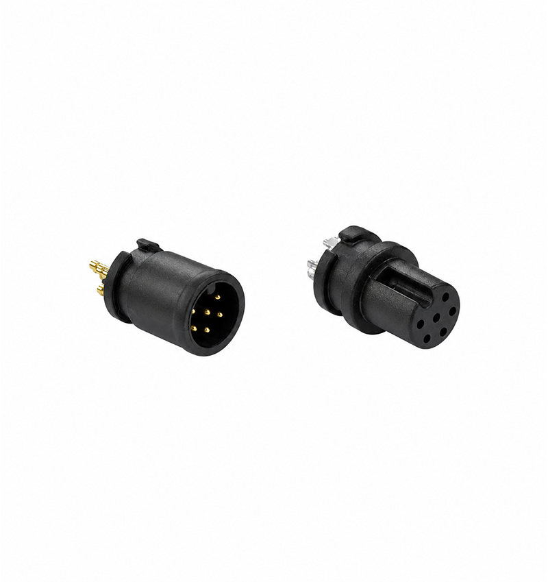
The M7-6P incorporates six conductive positions arranged within the mating interface.
On the pin-type component, the metal contacts are positioned inside the surrounding housing. The socket-type component provides corresponding openings to receive the matching contact arrangement.
Each position can be assigned to a separate circuit path according to the equipment wiring requirements.
The six-contact configuration may accommodate multiple signal conductors or other compatible electrical circuits, provided the connector's rated specifications meet the intended application.
The black exterior includes several molded structural features that define the connector's physical construction.
The recessed component uses a rounded barrel with a circular front opening. A raised section near the rear creates a change in housing diameter.
The projecting component has a shorter rear body and an extended mating section. Its front face contains six visible contact openings, while a longitudinal groove is formed along the outer surface.
The two housing shapes provide the physical geometry required for the corresponding connector interfaces.
The projecting connector features a molded longitudinal groove along part of its body.
This feature serves as a physical orientation reference during connector mating. The corresponding connector must have a compatible internal profile for proper engagement.
Correct positioning is especially important for multi-contact connectors because the electrical contacts must align with their designated counterparts.
Before inserting the connector, the mating surfaces should be inspected for damage or obstruction. The components should be brought together in the intended orientation without excessive force.
Metal terminals can be seen extending from the rear section of the connector components.
These terminals provide the electrical interface between the connector contacts and the intended circuit assembly.
Their arrangement must be considered when planning the installation layout. Terminal spacing, conductor assignment and the applicable joining method should be verified against the connector drawing.
For assemblies requiring direct board or wire connections, the actual termination type must be confirmed before installation.
The M7-6P can be selected for compatible equipment requiring six electrical contact positions.
Multi-Signal Connections
The contact configuration allows several signal paths to be organized through one connector pair when the electrical characteristics are suitable for the intended circuit.
Electronic Equipment Interfaces
The connector can provide a detachable interface between compatible electronic assemblies requiring six separate contact positions.
Control Circuit Wiring
Equipment using multiple low-contact-count control circuits may incorporate a six-position connector to group the required connections.
Modular Equipment Connections
The male and female construction allows compatible equipment sections to be connected through a removable electrical interface.
Model: M7-6P
Product Type: Circular Electrical Connector
Connector Gender: Male and Female
Contact Positions: 6
Housing Color: Black
Housing Shape: Cylindrical
Male Interface: Recessed Metallic Pin Contacts
Female Interface: Six Socket Openings
Mating Feature: Molded Longitudinal Groove
Rear Connection: Exposed Metallic Terminals
The recessed pin arrangement places the male contacts within the surrounding connector body rather than leaving them fully exposed at the front of the housing.
During equipment design, sufficient installation clearance should be reserved for both connector components.
The required clearance depends on the overall body length, maximum housing diameter, terminal projection and mating direction.
Any adjacent components should be positioned so they do not interfere with connector engagement or removal.
Actual mechanical dimensions should be obtained from the M7-6P dimensional drawing.
The connector must be matched to the electrical demands of the equipment in which it is installed.
Before use, confirm the rated voltage and current for each contact, as well as the permitted operating temperature.
Where several contacts operate simultaneously, the applicable current rating and any relevant derating conditions should also be considered.
Contact resistance, insulation resistance and dielectric withstand voltage are additional specifications that may be relevant to the intended circuit.
These performance values require confirmation through the manufacturer's technical documentation.
Q1: What does the M7-6P model designation indicate?
M7-6P identifies the connector model, with 6P indicating a six-contact configuration. The exact dimensions should be verified from the product drawing.
Q2: How are the six contacts arranged?
The contacts are grouped within a circular mating interface. The male component contains metallic pins, while the female component provides six corresponding socket positions.
Q3: What is the function of the groove on the connector body?
The groove forms part of the connector's mating geometry and helps identify the intended insertion orientation.
Q4: Can M7-6P connectors be used for electronic signal circuits?
Yes, they may be used in compatible signal circuits when the connector's electrical characteristics satisfy the application's requirements.
Q5: Are the contact pins exposed on the male connector?
The male contacts are located inside a recessed circular housing, rather than projecting beyond the front edge of the connector body.
Q6: Is the M7-6P connector compatible with other M7 connector models?
Compatibility should not be assumed based on the M7 designation alone. The number of contacts, contact layout, housing dimensions and mating geometry must match.
Q7: Does the connector have a specified waterproof rating?
The product image does not establish a waterproof rating. Any IP classification must be confirmed using the applicable product specification.
Q8: What technical information is required before placing an order?
Confirm the M7-6P model, male or female configuration, contact arrangement, mounting dimensions, terminal type, electrical ratings and required operating conditions.
 RELATED


Copyright © 2026 All rights reserved Sitemap
Technical Support:hzw
This website uses cookies to ensure you get the best experience on our website.



 WhatsApp
 Phone